The Experimenter's Protoboard comes as two similar halves so snap it in half. The important things to orient ourselves are the copper tracks and the row and column number, so don't worry about the alignment of the other writing too much.
.png?branch=prod)
Note, there is one copper trace that goes around the side of the board. Place the Tactile Button Switches on the board as shown above and solder in place. The trace labelled in orange above (that goes around three sides of the board) will be connected to the positive battery terminal and the trace labelled in black will go to the negative battery terminal.
The next step is to solder the IC socket in place. If you would like to make a slimmer version of the game you can eliminate the IC socket and header socket for the display, but this will make it much harder to debug and reprogram the game. The notch in the IC socket faces furthest away from the buttons so that pin 1 is in row 9.
.png?branch=prod)
Note how we've deliberately bridged pins 4 and 8 (remember we are looking at this from the back) to the busses running up the middle of the board - these will be our main power connections and this method makes wiring a lot easier.
To mount the OLED display cut the HM3230 female header strip at the fifth position so that you get a length of four pieces. This is soldered to the prototyping board using rows 8-11. The pin in row 10 is bridged to the right and the pin in row 11 is bridged to the left.
.png?branch=prod)
Then set up four resistors as shown: (NB: Excuse the red, not sure where these were originally pointing towards.)
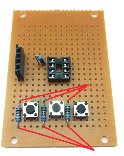
Take the top leg of the right hand resistor and attach it to pin 5 of the IC socket - this will be the first pin directly in line.

The rest of the legs can be trimmed but keep the offcuts to make some short links between the two top pins of the header socket and pins 2 and 3 of the IC socket.
Mount the battery holder as shown making sure the connections go to the positive and negative rails.
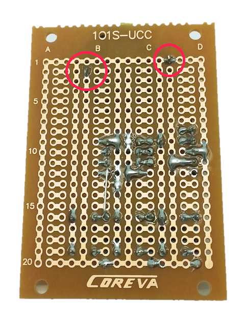
The last bit of soldering is to run some short pieces of wire from pins 6 and 7 on the IC socket to the other two pushbuttons (the easiest point to solder to is the exposed leg of the resistor).
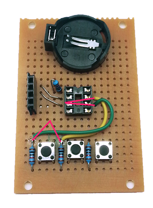
You can test fit the ATTiny85 IC and OLED display to make sure it all looks OK - be careful with the pins of the IC as they will bend very easily, especially when trying to remove the IC from the socket. A good trick is to install the IC into a second socket to protect the pins from repeated removal while you are programming and testing.
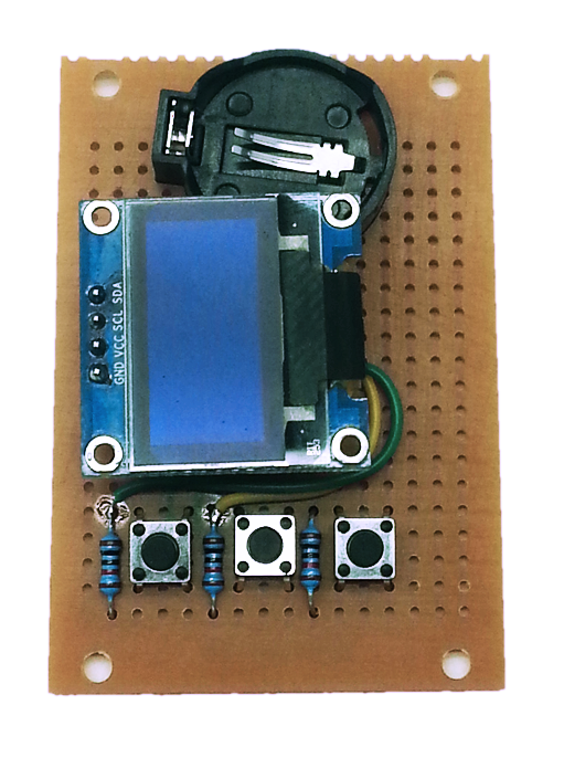
Do not insert the battery yet - we need to program the ATTiny85 IC and if this is done in place the programmer will put 5V on the battery which might damage it.


.png?branch=prod)
.png?branch=prod)
.png?branch=prod)


.png?branch=prod&format=webp&width=428)
