Thanks to the technology packed into modern electronics modules, we can create the Wired IR Extender with a couple of simple modules and a few other bits and pieces. The main components are the IR Receiver Module and an IR LED Module.
While it might appear that we could simply connect one to the other, the IR Receiver Module demodulates the 38kHz IR carrier, but the IR LED Module has no internal means of reapplying the modulation. So we need some extra circuitry to add back the necessary modulation.
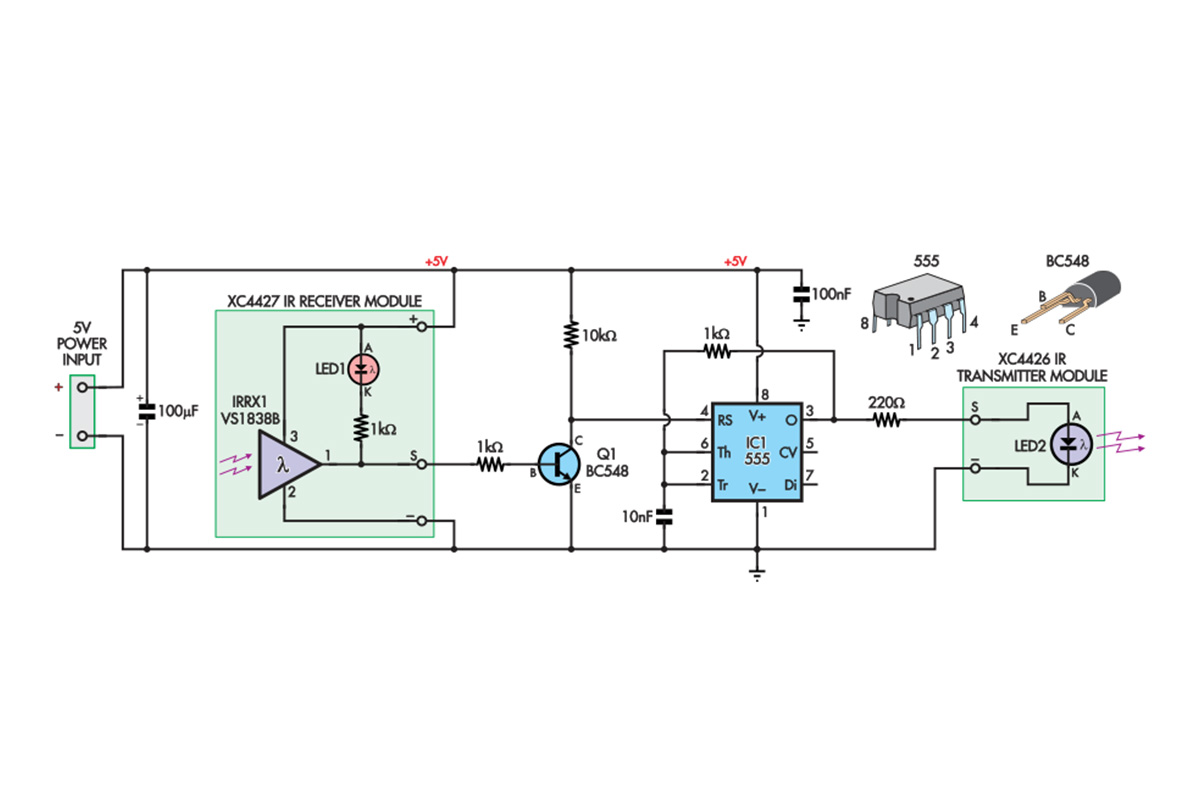
Fig.1 shows the resulting circuit. The 100µF and 100nF bypass capacitors help to reject noise on the 5V supply rail and keep its voltage stable. The IR Receiver Module contains the parts in the box on the left. The part labelled IR1 could be substituted by a separate component like Jaycar’s ZD1952 IR receiver.
The output (at the S pin) usually sits near 5V, but when an IR signal around 38kHz is detected, this pin goes low, lighting up the LED on the module. That is called an active-low output.
The 555 timer based circuit turns the active low signal from the IR Receiver Module into a 38kHz modulated active-high signal that can drive the Infrared Transmitter Module, which consists of nothing more than an IR LED (similar to Jaycar ZD1945) on a PCB.
NPN transistor Q1 and its two resistors (1kΩ & 10kΩ) form an inverter that turns the active low signal into an active high signal. With no IR signal falling on the IR Receiver Module, current flows into Q1’s base, turning it on.
When Q1 is on, it conducts current into its collector (C) and out of its emitter (E). The voltage at the collector is therefore low. If an IR signal is received, the S pin goes to 0V and no current flows into the base of Q1, so Q1’s collector voltage can rise to 5V due to current flowing through the 10kΩ resistor. That allows the 555 to oscillate and deliver a 38kHz-modulated signal to the IR LED.
The inverted signal from Q1’s collector goes to IC1’s RESET pin (RS, pin 4), so IC1’s output (O, pin 3) is low whenever there is no IR signal. However, when RESET is high, the 555 timer can operate. Its output will be high after the TRIGGER (Tr) pin goes below 1/3 of the supply voltage, then switches low when the THRESHOLD (Th) pin goes above 2/3 of the supply voltage.
The TRIGGER (pin 2) and THRESHOLD (pin 6) inputs are joined, and the 10nF capacitor is kept discharged when RESET is low by the 1kΩ resistor. So the 555’s output goes high as soon as RESET goes high.
The 10nF capacitor charges up from the OUTPUT through the 1kΩ resistor until the voltage on it (and thus the TRIGGER and THRESHOLD pins) reaches 2/3 of the 5V supply. The output goes low and the 10nF capacitor discharges until the 1/3 supply voltage point is reached.
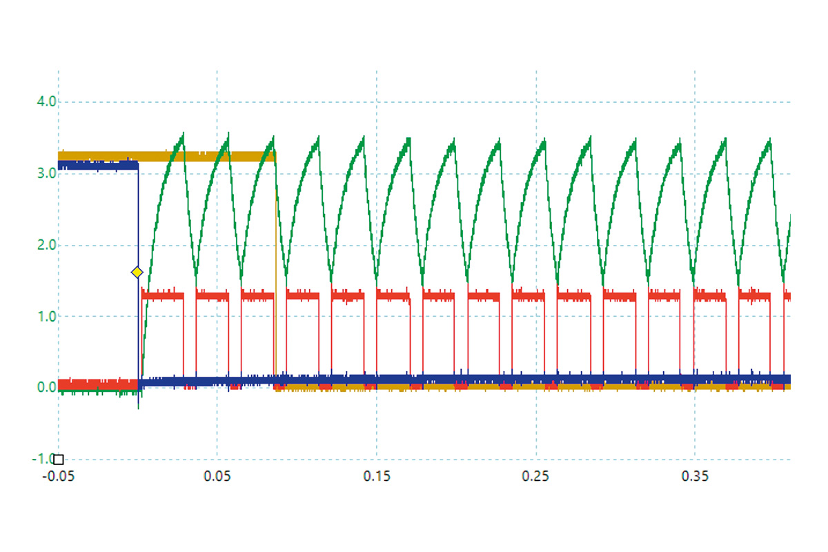
The cycle continues, with the 555’s output producing a 38kHz square wave. This signal is applied to the IR LED as long as the IR Receiver Module receives a signal.
Note that when there is no signal, current through LED1 must flow through both 1kΩ resistors. When a signal is detected and the S pin is near ground, current only needs to flow through one of the resistors. So you will see the LED’s brightness increase as a signal is received.
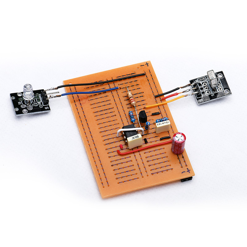


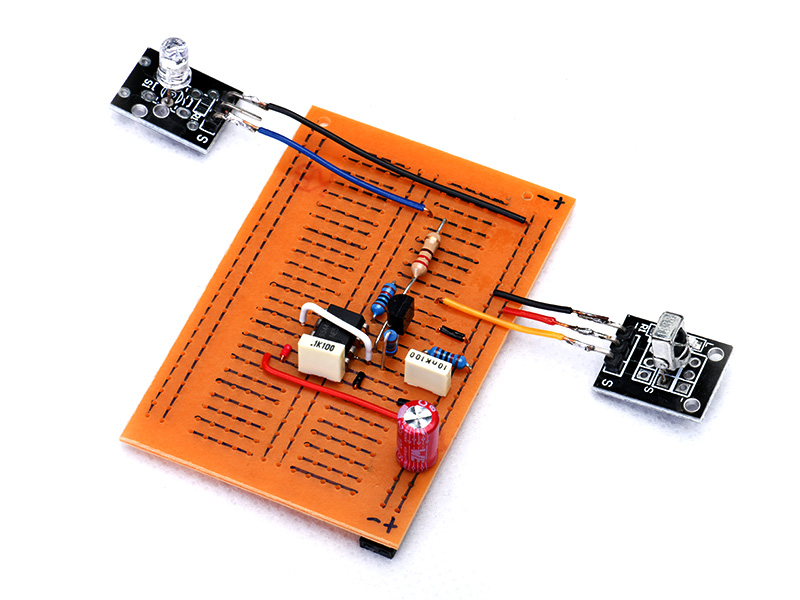
.png?branch=prod&format=webp&width=428)

.jpg?branch=prod&format=webp&width=428)