Progress Bar

Skip to main content

Jaycar
...

Mailbox Notifier

Mailbox Notifier

Difficulty
Test & Tools

Summary

Eagerly waiting for a letter to come in the mail, I was held back checking the mailbox every day, which interrupted my ability to go into town when I needed (just in case I missed the letter arriving)

I figured "there must be a better way!" - and set out to design a system that can alert me on the phone when the mail comes in.

Materials Required

1Wi-Fi Mini ESP8266 Main BoardXC3802
13 X AA Side by Side Flat Battery HolderPH9274
1SPDT 250V 5A Standard Micro Switch with LeverSM1039
1Light Duty Silicone Hook Up Wire 8m Handy Pack BlackWH3036
1Jiffy Box - Black - 83 x 54 x 31mmHB6015
1Eclipse AA Alkaline Batteries - Pack of 4SB2425

The design of this system has to:

  1. Be triggered by a new envelope entering the mailbox.

  2. Alert me on my phone, no matter where I am.

  3. Be relatively long-lasting, without me having to replace batteries every day.

It really comes down to two components, mail detection and mail notification and they are both exceedingly simple to do; I figured I can use the https://ifttt.com service with the trusty ESP8266

We've tried to seperate this project into two phases so that you can understand how we are going from design, to prototyping, to assembly.

Below are some notes and information from when we were prototyping the project, so that you have a better understanding of how they all fit in, and you can prototype yourself to follow along.

If you want to just get to building the project, head straight to the Assembly Section

IFTTT is a super simple service that we've used in our projects before. It can be a little limited in some regards, but there's no complaints for a free lunch and ifttt is completely free to use. It stands for "If This Then That" if you weren't sure what it meant already.

Head to https://ifttt.com and create an account, and you can install the ifttt app on your phone too (though play or apple store).

When you make an account, you want to create an applet

Change the +This term to be a Webhooks service. You want to trigger when you receive a web request and set the event name to:

ESP_reset

Change the +That term to be a Notifications service. You want the action to be send a notification from the IFTTT app, and you can set the message to anything you want, such as:

You've got mail at {{OccurredAt}}

The {{}} indicate a special variable, that for this example, will be filled with the time and date that the event happened.

What you've just created is an "applet" in IFTTT lingo.

To test it, make sure that you have the IFTTT app on your phone, and that it is logged in to your account.

Click on this link to open up the webhooks service page: https://ifttt.com/maker_webhooks

To access this same page manually, from the home page:

  1. click on your profile in the top right

  2. click "My services"

  3. click "webhooks"

Now click the large Documentation button in the top right.

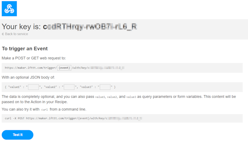
You will come to a page that looks like this:

Provided that everything is set up right, you should be able to change the {event} code to be ESP_reset then press the Test it button, which will cause your phone to vibrate.

Play around with ifttt and see what other services they can do, it's a great website, and the email/gmail service could also come in handy for this project.

Deep sleep and reset

Deep sleep mode is very easy to test with the ESP; try out some code like this:

void setup() {
    Serial.begin(115200);
}

void loop() {
    for(int i = 0; i < 5; i++){
        Serial.println(i);
        delay(500);
    }
    Serial.println("goodnight!");
    ESP.deepSleep(0);
}

You should find that it does exactly what you expect it to: it will count down from 5 then say "goodnight!".

Once it reaches the ESP.deepSleep(0); line, it will not execute again, and for all intents and purposes could be considered as though it was turned off. It won't run the loop again and won't send serial data.

To reset the device, just bridge the RST pin to GND for half a second, the ESP should start counting down again.

With assembling, it is important to remember that the ESP must be within range of your WiFi, and might not be able to get any signal when it is within your metal letterbox. We are using 8m of light duty silicone wire so that we can seperate the switch from the esp and atleast try to get the ESP 4 meters closer to the house WiFi. Results may vary, so play around and send us a picture of what you've created.

Battery Holder on lid

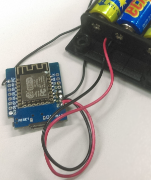
The battery holder is the easiest to do. 3 AA batteries at 1.2V is just 3.6v which is perfect for our ESP8266

Use some hot glue, blu-tack, double-sided tape () or otherwise to stick the batttery box to the lid of the enclosure.
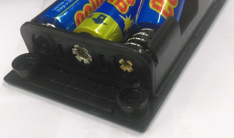
It should fit pretty snug just behind the screw portals.

Once the glue has set, you can solder the positive (red) lead to the ESP8266's 5V pin and the negative (black) lead to the ESP8266's GND pin

Microswitch to ESP

As expected from when we were prototyping the design, the microswitch just connects between GND and RESET

The microswitch is nothing spectacular, it has 3 connections:
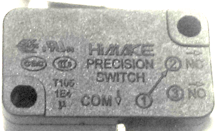
  • Common

  • Normally Closed

  • Normally Open

We want GND and RESET to be normally OPEN, so that when the switch is press, it will CLOSE the connection, and reset the ESP:
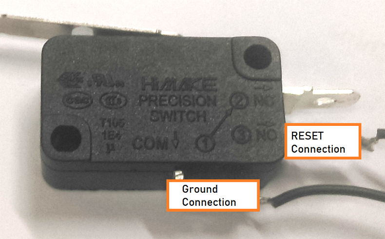
Cut a decent length of your silicone wire and then cut in half again (or just cut the whole thing in half for the whole 4 meters); you will need two lengths of the same distance to reach between the switch and your ESP.

Connect as follows, using one length of black wire each:

Connection from

Connection to

Microswitch COM terminal

ESP8266's GND pin

Microswitch NO terminal

ESP8266's RST pin

Programming

The programming for this device is simple, once you have downloaded the code from the link at the top of this document, you can use the arduino IDE to upload the mailbox.ino code onto your {XC3802}. If you haven't done this before, be sure to read the manual on how to do so on the XC3802 product page.

  1. Make an IFTTT account if you have not already.

  2. Get your maker_key from the Assembly instructions.

  3. put in your wifi_ssid and wifi_pass into the code, along with your maker_key (Keep the TRIGGER_NAME to be the same)

You should be able to find that every time you turn the ESP on (ie: connect it to computer or to batteries) you will get a notice on your phone.

It is a little annoying when programming to always get notifications from the device right infront of you, but most of the debugging is done, so you should be able to just confirm that it works as intended, then go place it in your mailbox.

Closing the lid
Once the microbit's all soldered up and programmed, you can use some double sided tape or hot glue to glue it into the enclosure, and close the lid, with the switch leads coming out from one of the sides.

It's not strictly waterproof but should do ok in sheltered environments. if you need more waterproofing you might best put it in a sandwich bag or otherwise. The outside environment is tough, so keep that in mind.

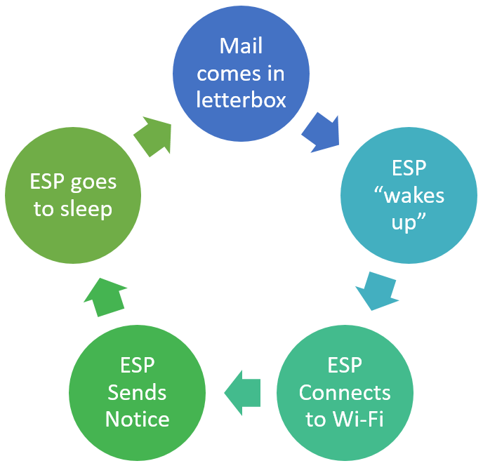
As the letter comes in and triggers the switch, the ESP will effectively "turn on" (via a reset).

This causes the esp to send you a "You've got mail" notification on your phone.

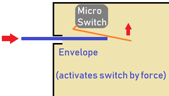
The best place to put the switch is such that the whole weight of the letter pushes down on the part of the micro switch arm as far away from the base as possible; this should have enough torque to activate the switch.

If you find that the letter isn't doing it via gravity alone, try mounting it on the roof so that the act of the letter going into the mailbox is what triggers it.

Play around with the design and see how long it lasts. If you have any improvements, feel free to put them as an issue on the github project page.

Future Improvements

  • Use ZM9012 for some solar power to extend the battery life further than the batteries themselves, or even use rechargable batteries SB1737

  • You could use the record-playback module (XC4605) to say a nice message to the delivery person, but that will drain the batteries quite a lot.

  • A nicer power design would be good, and the original design was intended to be a self-bootstrapped design, where the ESP would be fully isolated from the batteries, until the microswitch turns it on, which then would activate it's own FET to keep it on while it worked. This design means that it would be able to keep itself powered for as long as possible, and then drop to 0 uA, but time got the best of us.

Similar projects you may be interested in

Test & Tools
Laser Beam Timer
Difficulty

Jaycar-RCT-Hero
Test & Tools
Resistor & Capacitor Tester
Difficulty

Portable Soil Moisture Meter
Test & Tools
Portable Soil moisture meter
Difficulty

Test & Tools
Wireless Garden Monitor
Difficulty