Progress Bar

Skip to main content

Jaycar
...

How to Build a Self-Toggling Relay

How to Build a Self-Toggling Relay

Difficulty
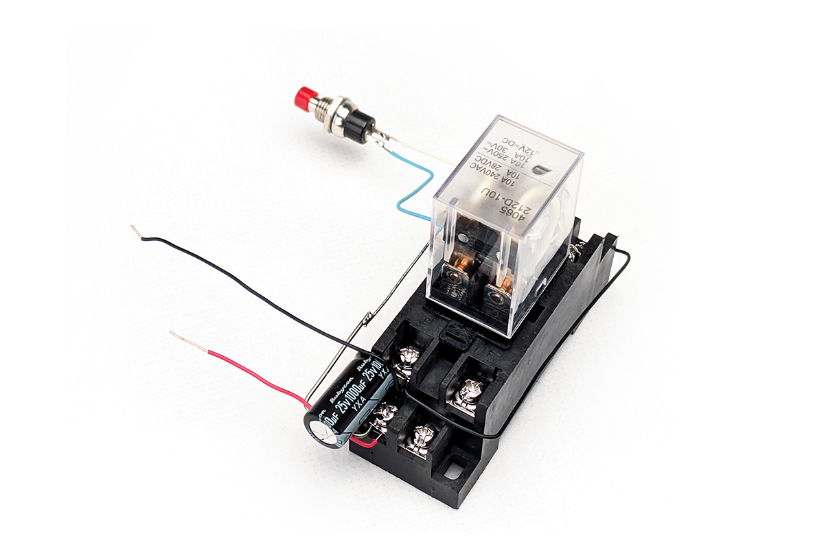
selfTogglingRelay-Hero-1200x800.jpg

Summary

This design achieves that goal using just one DPDT (double-pole, double-­throw) relay, a common type. It provides a free set of ‘dry’ contacts, meaning they are not connected to any circuitry or a power source. You are free to do whatever you want with them, within the limits imposed by the relay’s ratings.

It might be possible to build this circuit using a single-pole (SPST) relay if the thing you wanted to switch was completely independent of the relay’s power source. Still, DPDT relays are inexpensive, and using a free set of contacts is safer.

Materials Required

112V DPDT Power Relay - 10A 240VAC/24VDC ContactsSY4065
1Red Miniature Pushbutton - SPST Momentary Action 125V 1A ratingSP0710
11000uF 25VDC Electrolytic RB CapacitorRE6230
11k Ohm 0.5 Watt Metal Film Resistors - Pack of 8RR0572
1150 Ohm 1 Watt Carbon Film Resistors - Pack of 2RR2554

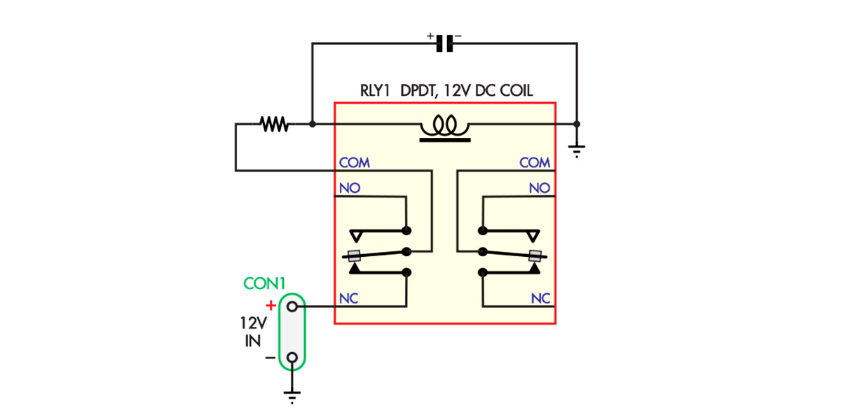
Our design relies on a property of relays that we can demonstrate with the circuit in Fig.1. A capacitor is connected across the relay’s coil and charged via a resistor fed from the normally closed (NC) contact.

fig1-PageImage-1200x600.jpg

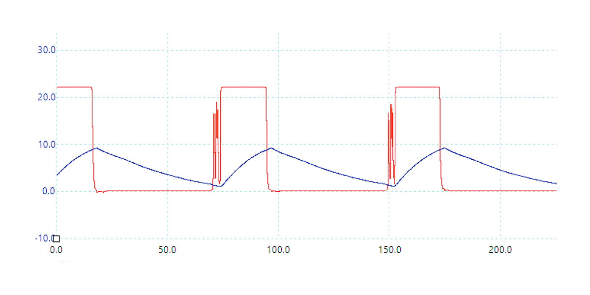
When power is applied, the capacitor charges until the relay’s armature pulls in. The contacts open, the capacitor discharges until the armature drops out, and the cycle continues. It forms a ‘relaxation oscillator’. Scope 1 shows the resulting waveform for the Jaycar SY4065 relay that we are using.

The blue trace is the voltage across the coil, while the red trace shows the relay state changing. Although it is a 12V relay, the contacts open at around 1V and close at around 9V. The relay data sheet lists those as the ‘must release’ and ‘must operate’ voltages.

As you can see from the scope grab, this circuit toggles at around 10 times per second, so this relay’s minimum 100,000-cycle operating life would be reached in about three hours!

If you want to apply this design to another relay, we recommend checking its datasheet first.

scope-PageImage-1200x600.jpg

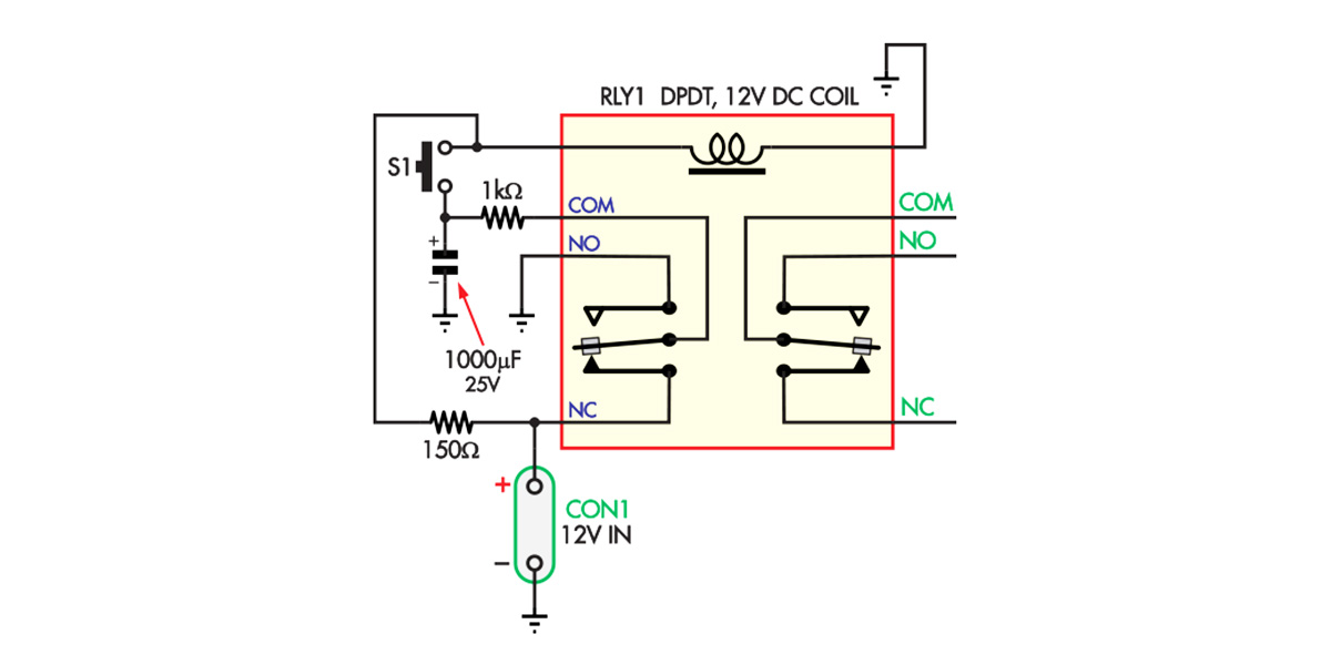
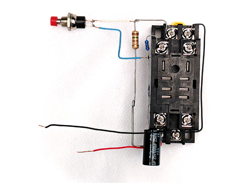
Fig.2 shows the circuit for the Self Toggling Relay. RLY1’s coil has a resistance of around 160Ω, and when power is applied, it has around 6V across it. That is less than the must-­operate voltage, so the relay remains off.

fig2-PageImage-1200x600.jpg

The capacitor charges up via the relay’s NC and COM contacts, reaching close to 12V after a few seconds. Pressing S1 places the capacitor directly across the relay coil.

Since it now has 12V across its coil, the relay pulls in and the contacts change over. When S1 is released, the coil voltage returns to around 6V, above the must-release voltage.

The capacitor now discharges to 0V via the NO and COM contacts. This takes around a second, since it will have discharged slightly while S1 was pressed. If S1 is pressed again, the reverse happens and the relay drops out, returning to the earlier state.

Effectively, we are using the hysteresis of the relay coil voltage (the difference between the must-operate and must-release voltages) to maintain its state and using the capacitor to change the state. The capacitor charging time sets the maximum toggling rate, about once per second for the chosen components.

Since the relay is not operating at its full rated voltage, the contacts are not pulled in as tightly as they would otherwise be. This means the relay may be more susceptible to vibration and shocks and might drop out (or in!) if subjected to rough conditions.

Also note that if power is removed, the relay will return to the released state almost immediately; this is a nice safety feature.

top-PageImage-800x600.jpg

If you need another button that will always switch the circuit on or off, you could add another pushbutton, 1000µF capacitor, and 1kΩ resistor and wire them up in almost the same fashion.

In this case, instead of feeding the 1kΩ resistor from the relay’s COM contact, feed it from 12V for an ON switch or 0V (ground) for an OFF switch. That gives a circuit that can generate the necessary impulse, but it will always have the same effect instead of toggling.

Keep in mind that pressing more than one switch simultaneously might connect capacitors charged to different voltages, possibly running high currents through the switch contacts and damaging them.

The 150Ω resistor value was chosen to set the coil voltage between its must-­release and must-operate voltages. For other relays, a resistor with a similar resistance to the relay coil is a good starting point. By the voltage divider equation, this will put about half the supply voltage on the coil. If the datasheet does not mention a figure, measure the coil resistance with a multimeter.

Note that we used a 1W resistor here; you should check the power dissipation if making circuit changes. Your circuit should run from the voltage the relay is rated for. Don’t try to power a 5V relay from a 12V supply!

An early prototype we built used a smaller relay and we found that a 100µF capacitor could provide enough impulse to toggle the relay. The exact value depends on the relay, so we advise experimentation to find a capacitor value that works consistently.

The second resistor (1kΩ in our case) must have a high enough value to avoid substantially changing the coil voltage while the pushbutton is pressed. A value at least five times higher than the first resistor should work well.

The combination of the 1kΩ resistor and 1000µF capacitor (as used in our circuit) dictates the maximum rate at which the pushbutton can toggle the relay. Larger values will mean a longer wait time between presses.

selfTogglingRelay-Hero-1200x800.jpg

Similar projects you may be interested in