Installing Trailer Lights With a Complete Kit
Summary
In this weekend project, we show you how to replace stop/tail/turn lights and wiring on a trailer. This also applies to lights on your caravan or RV. First, we show you how to install LED lights with components purchased separately. Second, we show you how to install a trailer light kit with wiring loom. We then discuss replacing individual lights, including number plate lights.
Table of Contents
Tools:
1 x TD2022 7 Piece Screwdriver Set
1 x TD2192 5 Piece Combination Spanner Set
1 x TD2800 20V Cordless Drill Set
1 x TH1984 Heavy Duty Pliers
Start by removing the old lights. We cannot be too specific about this because of the variety of designs, but in general, there will be two or more bolts in each light cluster with nuts on the other side of a plate of metal. Some designs do use self-tapping screws from the front, and some poorly-placed lights may be attached to areas where there is no access for nuts and bolts, like hollow section steel instead of plate.
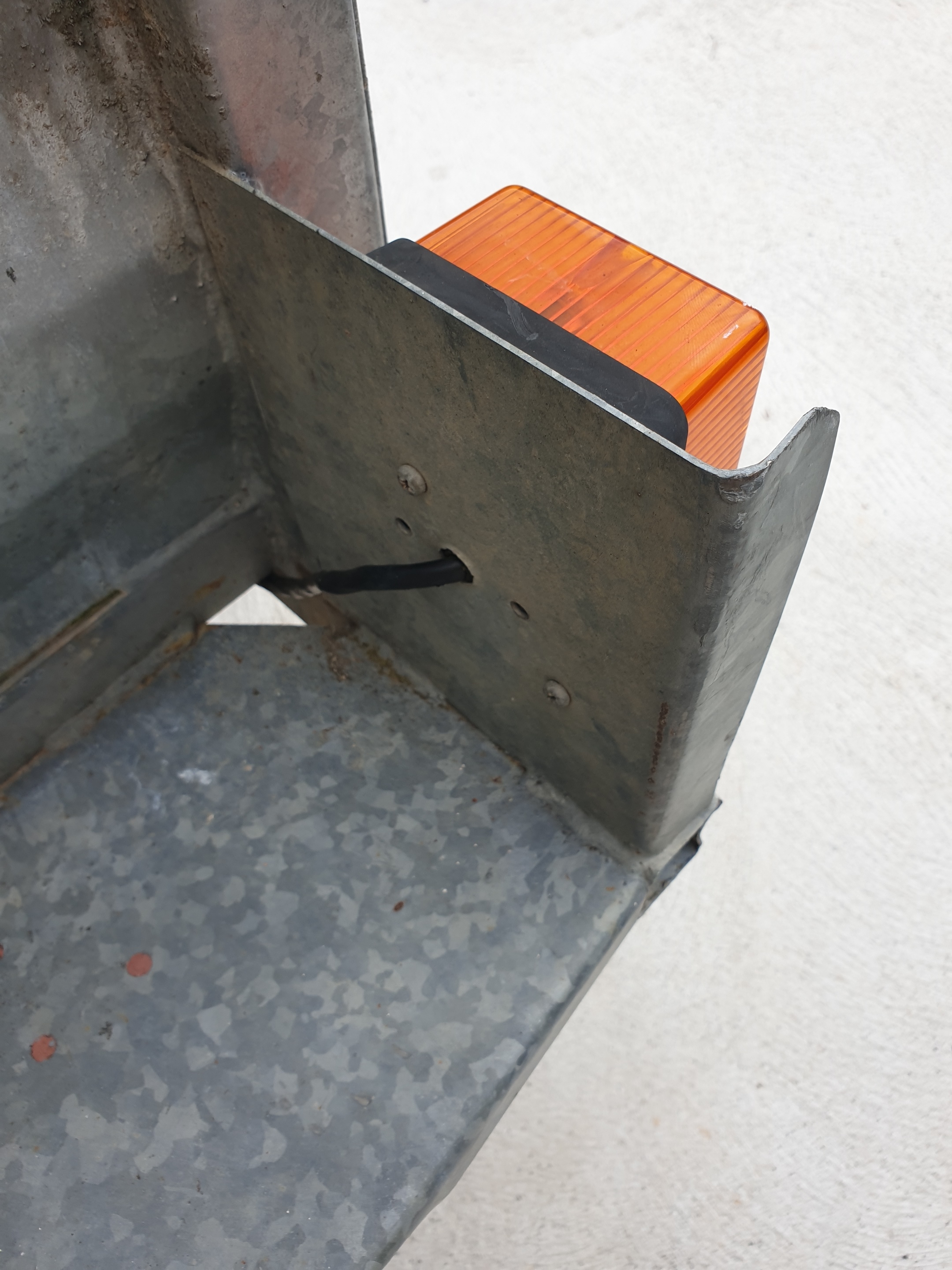
Cut the wires close to the light cluster, and at the plug near the drawbar. Pull out any wiring that you can, then get under the trailer and look for any more.
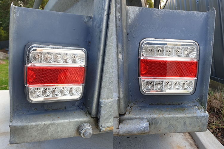
Having removed the old lights, hold the new lights up to the mounting points to see if screw holes align. These lights have a plug in the back while the old lights did not, so we need to enlarge what was the wiring hole to take the plug. For this, we used a step drill. We also needed two new mounting holes. We later sprayed everything with a coat of cold galvanising spray to keep rust away.
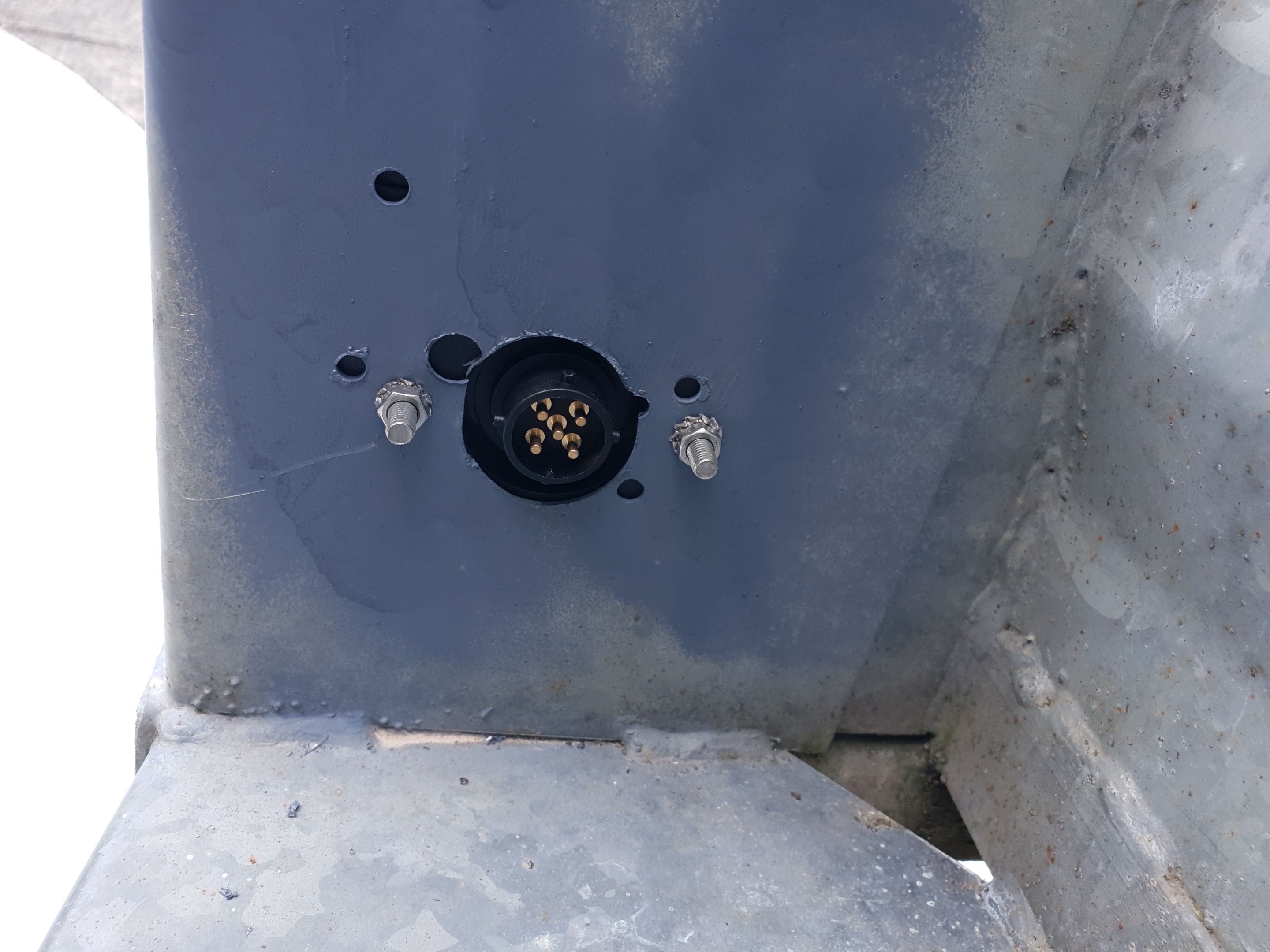
NOTE: We mounted our lights with the number plate light facing downward, because we are not using it. If you are using the number plate light, the bolts will be vertical, not horizontal like ours are.
Next, mount the new lights. Do up the nuts over the bolts moulded into the light fittings. You may wish to add some thread fixing compound to give extra insurance against loosening. Repeat this process for both sides.
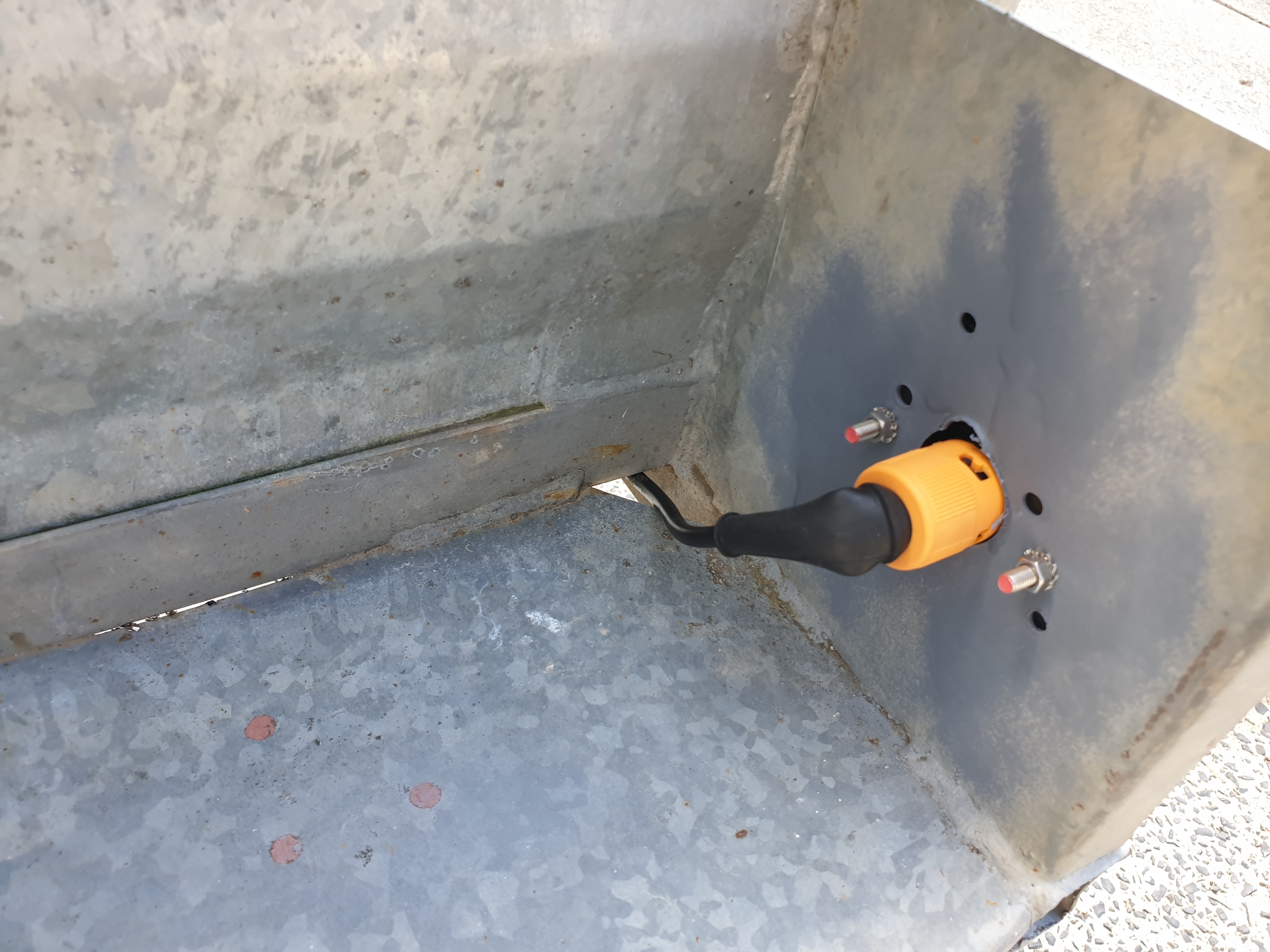
Feed the plugs from the ends of the wiring loom from the underside of the trailer to the light fittings. Keep the left and right colours in mind: The Yellow plug is the left light, viewed from the rear, while the green plug is the right light. On some trailers, the holes to run the wire will not take the plugs. You can either enlarge them, or go around. Screw in the connectors to the light fittings.
Under the trailer, use cable ties and adhesive cable tie mounts to secure the cable to any convenient part of the trailer chassis.
Note if you use P-clamps instead of cable ties, P-clamps are great but need to be screwed in with self-tapping screws, so do not use them on the underside of the trailer floor sheeting! Only use them on areas where the other side of the screw will not be a problem, like angle or box section parts of the frame.
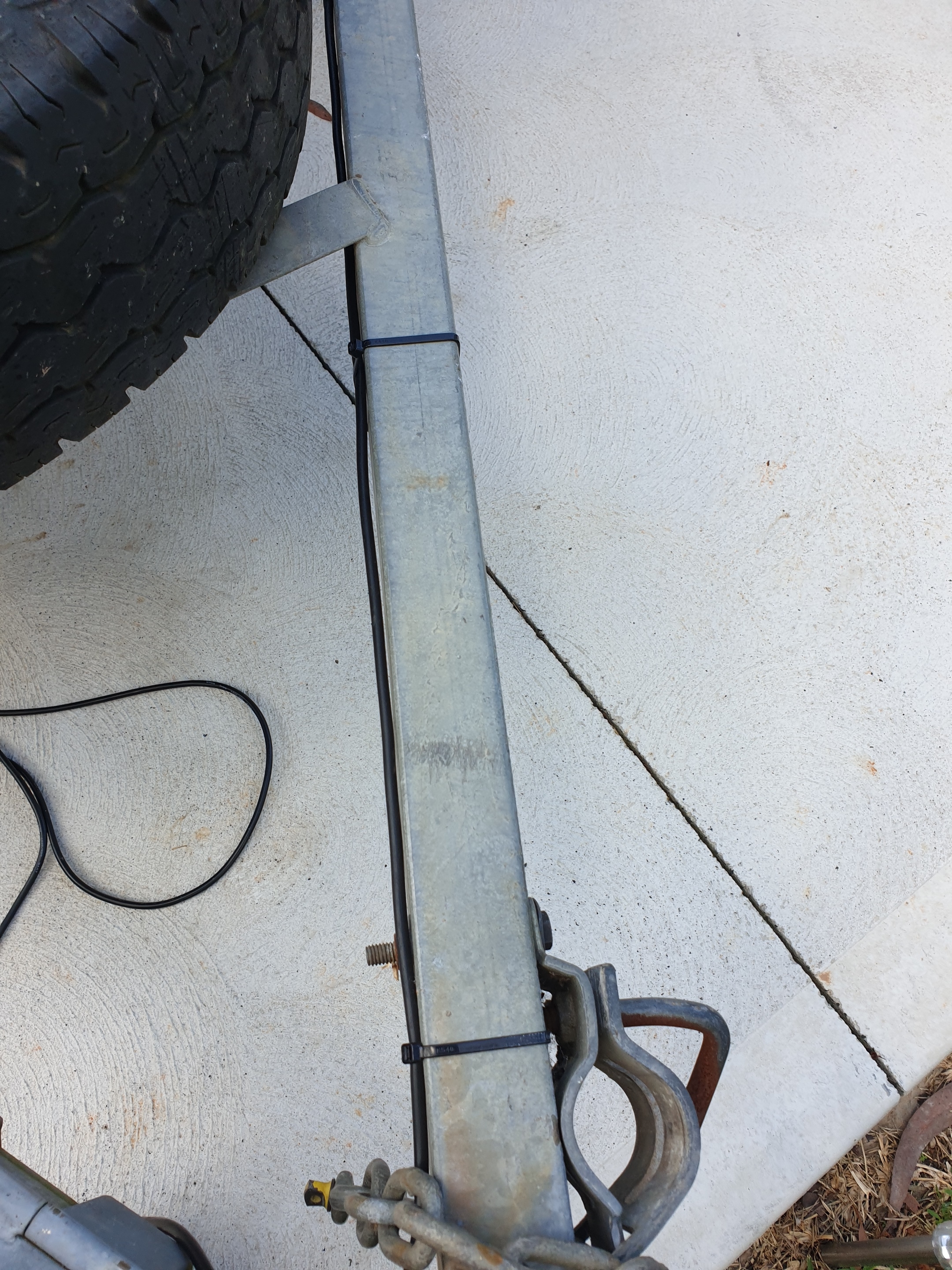
Choose now whether you want to coil up the spare cable under the trailer, or at the end of the drawbar. If you are keeping it hidden, run the cable out long enough to reach the towing connection, and coil up the excess, securing it with ties.
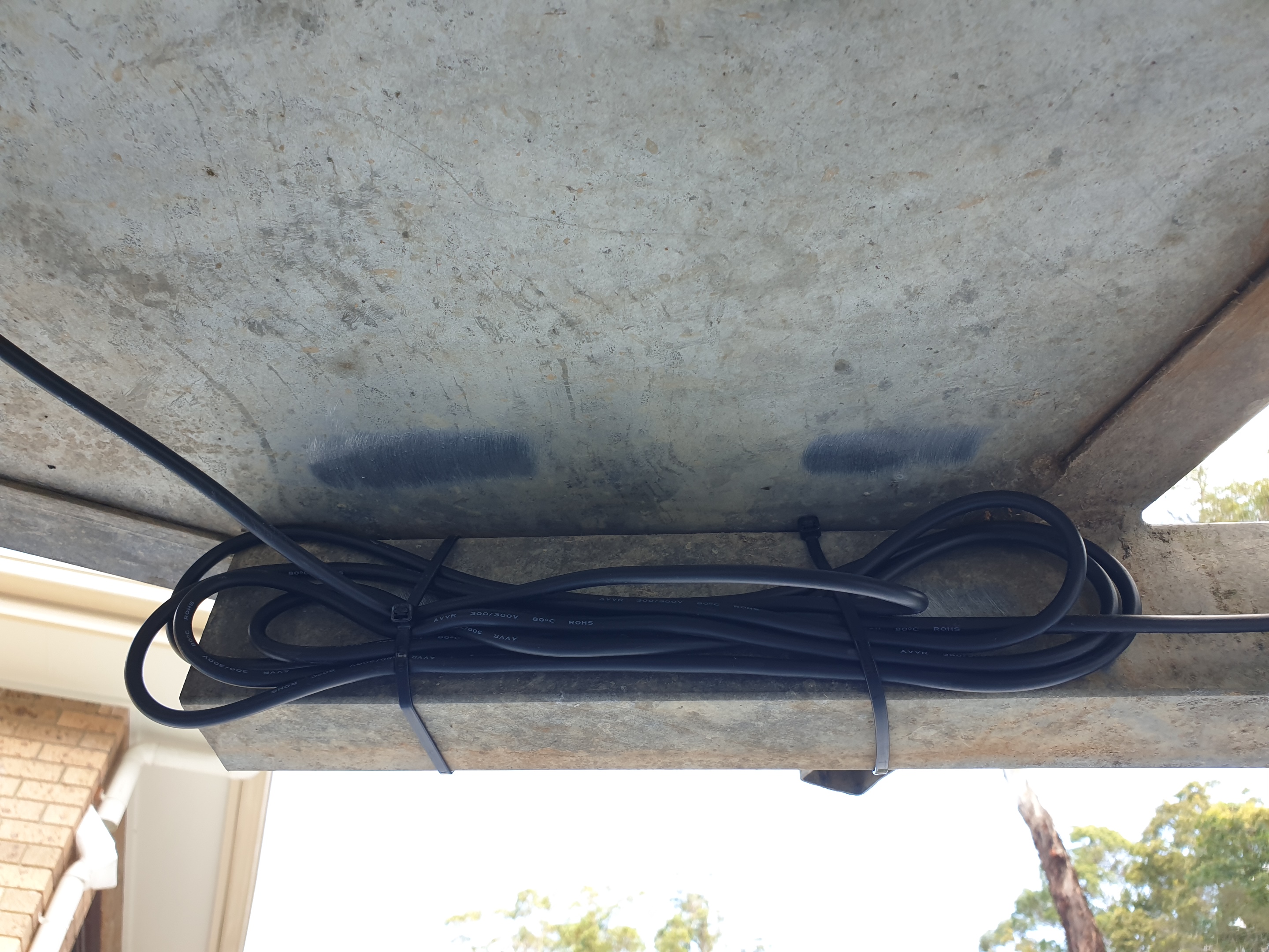
Continue running the cable wherever you can and securing it with ties or clamps until you get to the drawbar. Here, you must work on the inner side of the drawbar to avoid cable damage later. At the end, you will have some spare cable if you chose not to secure it under the trailer earlier. Coil up the excess with enough left to reach the towing vehicle's connection, and secure the excess coil with cable ties. That's it, you're done!
To finish off, you might like to cover all of the exposed cable with split loom tubing. You will have to do this before fully tightening the cable ties, but hopefully you read this guide fully before starting anyway! Split-loom tubing covers the wire and adds extra abrasion and impact damage resistance. It is a ribbed tube similar to vacuum cleaner or pool cleaner hose, but smaller, with a slit running its length. It can be cut with a knife, then pressed over the wire to help protect it.
There is not always a reason to replace all of a trailer's wiring. If you have faulty lights and do not know whether it is the wiring or the lights themselves, it is probably best to replace the lot. However, there are times when you know that a light is faulty rather than wiring. For example, when it was working fine before you backed into a steel bollard and smashed the light. In these cases, replacing the light can be done by buying just the light pair, and soldering the new tails for the plugs onto the old wiring, provided you are sure of the correct wire colours. You can also use crimp connectors, if soldering is not an option.
Having a light for the number plate on a trailer is a legal requirement in every state and territory of Australia to the best of our knowledge. The trailer lights featured here have a side light built in that is active whenever the tail lights are on. On some trailers, this means mounting the number plate next to the light cluster, and the job is done. On other trailers, however, the lights are not in a position where this is possible. Take our example trailer: It has plates for the lights which are recessed to protect the lights against mechanical and impact damage. This means side lights are not practical.
In these cases, a separate number plate light is needed. There are many designs and the range evolves over time, but at the time of writing, this was the product we went with. It is a 12V LED light with two housings in the package - one for direct mounting, and one for side mounting. With the side-mount housing, this forms a dedicated number plate light which can be placed wherever the number plate is. However, there is some extra wiring needed. It will need to connect to the trailer wiring on the tail light connection. As such, the complete kit featured in the second instruction set is unsuitable - it has complete, sealed wiring. You could cut it, but that starts to defeat the purpose of the complete kit. It is much easier to get individual components and customise the wiring.
Prepare your number plate light by soldering some wires to the fly leads on the light. You can use twin-core like speaker wire, or individual wires if you like, but make sure you can identify the positive and negative wires at the other end. This twin-core speaker wire has a trace or stripe for that purpose. We soldered and used glue-lined heatshrink (see further on).
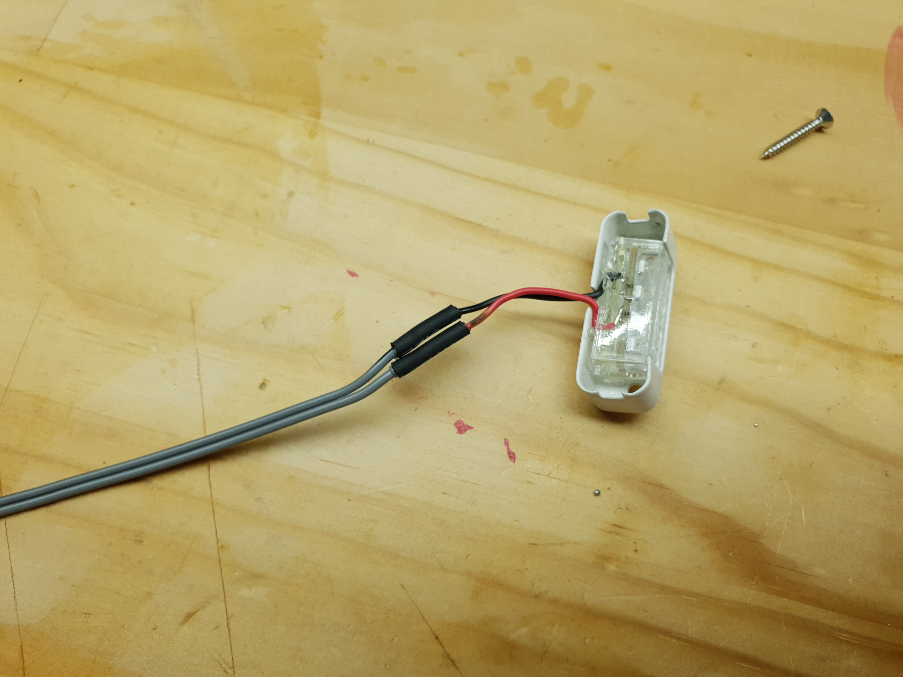
You can use crimp connectors but these wires are a bit too small. If you have no soldering tools, use the end-to-end crimp connectors and make sure you get the smallest wire size.
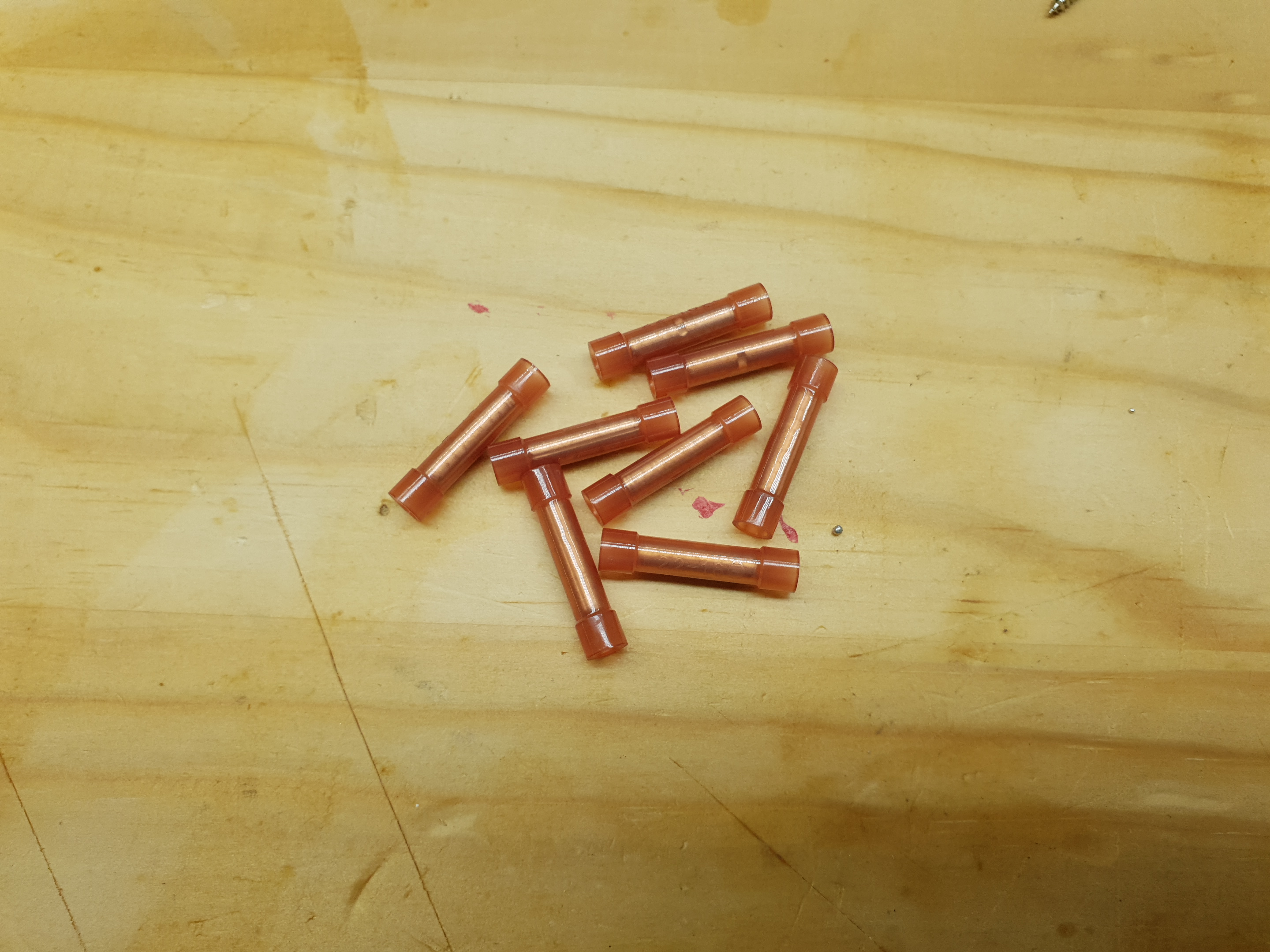
Also, double or triple up the LED wire in the connector, because it is quite small.
While there is a long-standing view in some circles that soldering is always better than crimping, that is not automatically true. A bad solder joint will be worse than a good crimp joint, and a good crimp joint is functionally just as good as soldering in many cases. The key is what makes a good crimp joint. For the record, soldering can embrittle the wiring at the heated point, and so the metal can fatigue more in some situations, too.
A good crimp joint requires the right tool, the right technique, and the right crimp connector. If any one aspect is lacking, the whole joint is lacking. Firstly, connectors. Connectors must be matched to the wire size to produce a good joint. The wire must fill the connector and not leave much space inside. If the wire is too small for a given connector, as it sometimes is due to factors you cannot control, then strip extra wire and fold it over until the connector is filled. The best connectors are ones which surround the cable entirely, like tubular ones, or the u-shaped type which fold over onto, and squash, the wire.
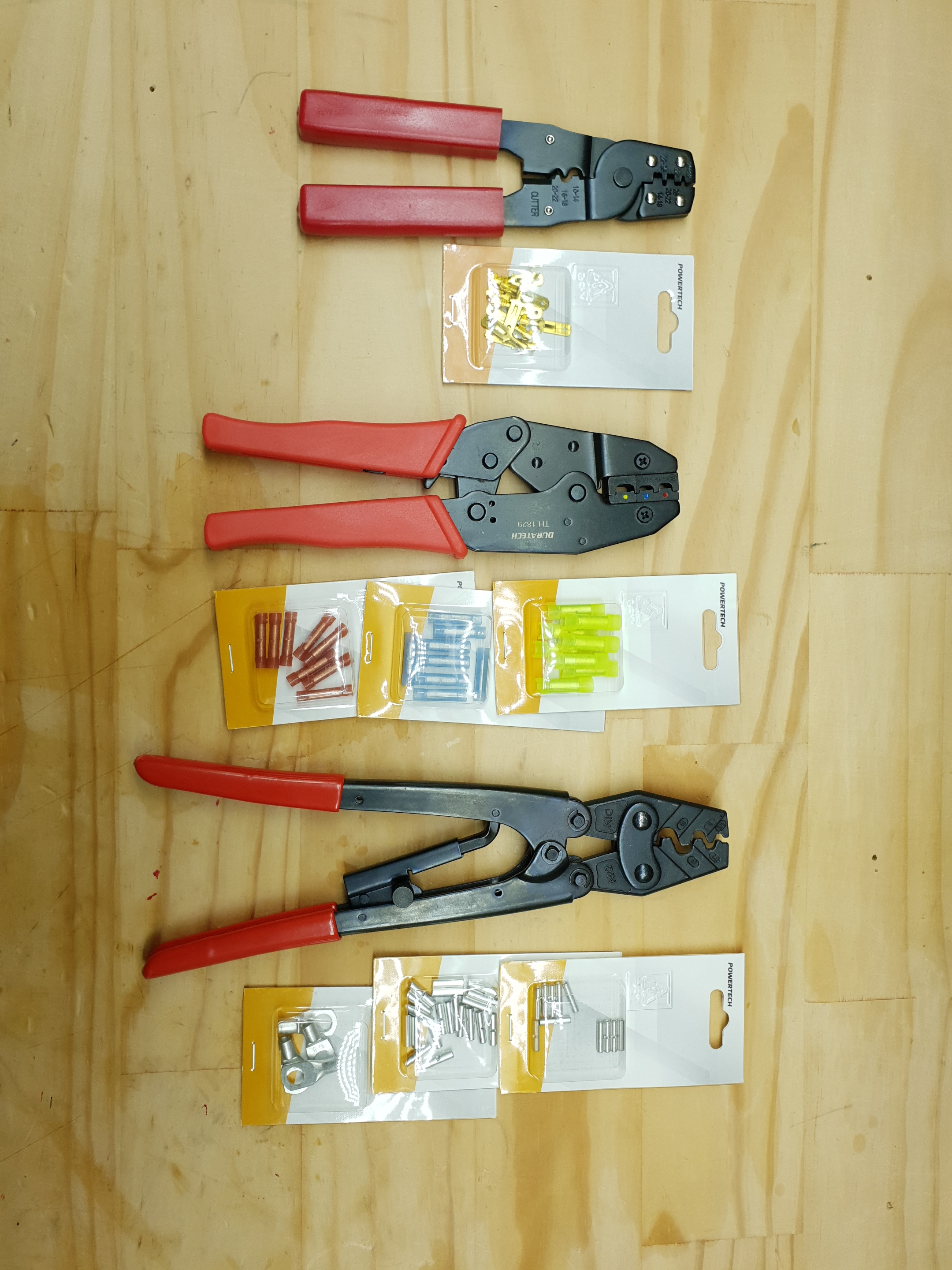
The second factor is the right tool. While the simple sheet-metal multitool often supplied with crimp connector kits looks easy to use, it does a poor job. A far better option is a dedicated tool. For the tubular type connectors, which are the colour-coded red, blue, and yellow ones (depending on wire size), the tool pictured with the coloured dots applies much more pressure than the multitool, and at two points along the connector rather than one. The other tool pictured is for the uninsulated u-shaped crimp connectors, and has a carefully shaped die, and enough width to produce a good join, This one is not ratcheted because it is meant for smaller connectors.
That leads us into technique, which has partly been covered above. The wire must fill the connector, and the crimp must be firm enough without squashing the connector so far that it is weakened. That, along with the crimp being the wrong shape to properly clamp the wire, are the main reasons never to use the flat jaws of pliers, multigrips, or vice grips to crimp these connectors. So, using the right tool ensures the right amount of 'squash' to make the connector work well.
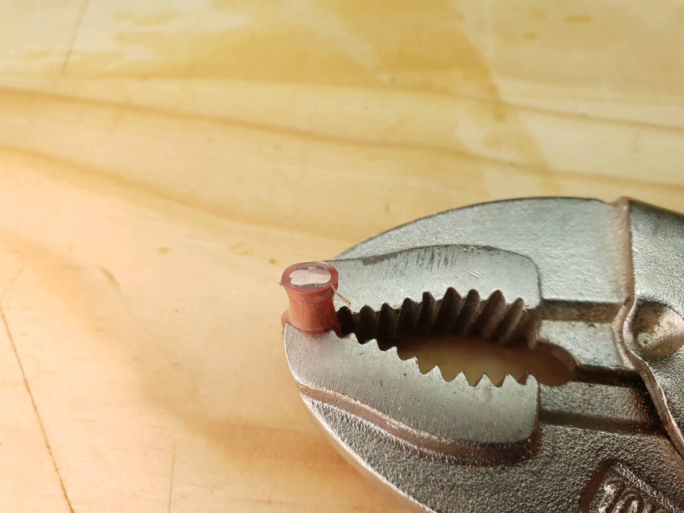
If done well, a crimp connector is very secure. Here is one we did with one of the tools pictured above, then cut in half. We filed and sanded it so you can see clearly how dense the metal really is.
Finally, crimp connectors often benefit from having glue-lined heatshrink added like solder connections do. It helps keep water out and adds strain relief
Similar projects you may be interested in

