Arduino Clap Light
Summary
The “Clapper” is a sound-activated switch introduced in the USA in the 1980s. It is a box that plugs into a power point and allows two appliances to be connected. According to the motto, “Clap on! Clap off!”, you could simply clap to switch an attached device on or off.
It toggled one appliance on or off when two claps were detected. Another appliance would respond to three claps. By some accounts, it could be too sensitive, reacting to other sounds or even people talking.
Most people used it to control a light or lamp since they are unlikely to cause harm if switched on or off at the wrong time. This simple project provides a similar function.
Materials Required
| 1 | Duinotech Leonardo r3 Main Board | XC4430 |
| 1 | Remote Controlled Mains Outlet Controller | MS6148 |
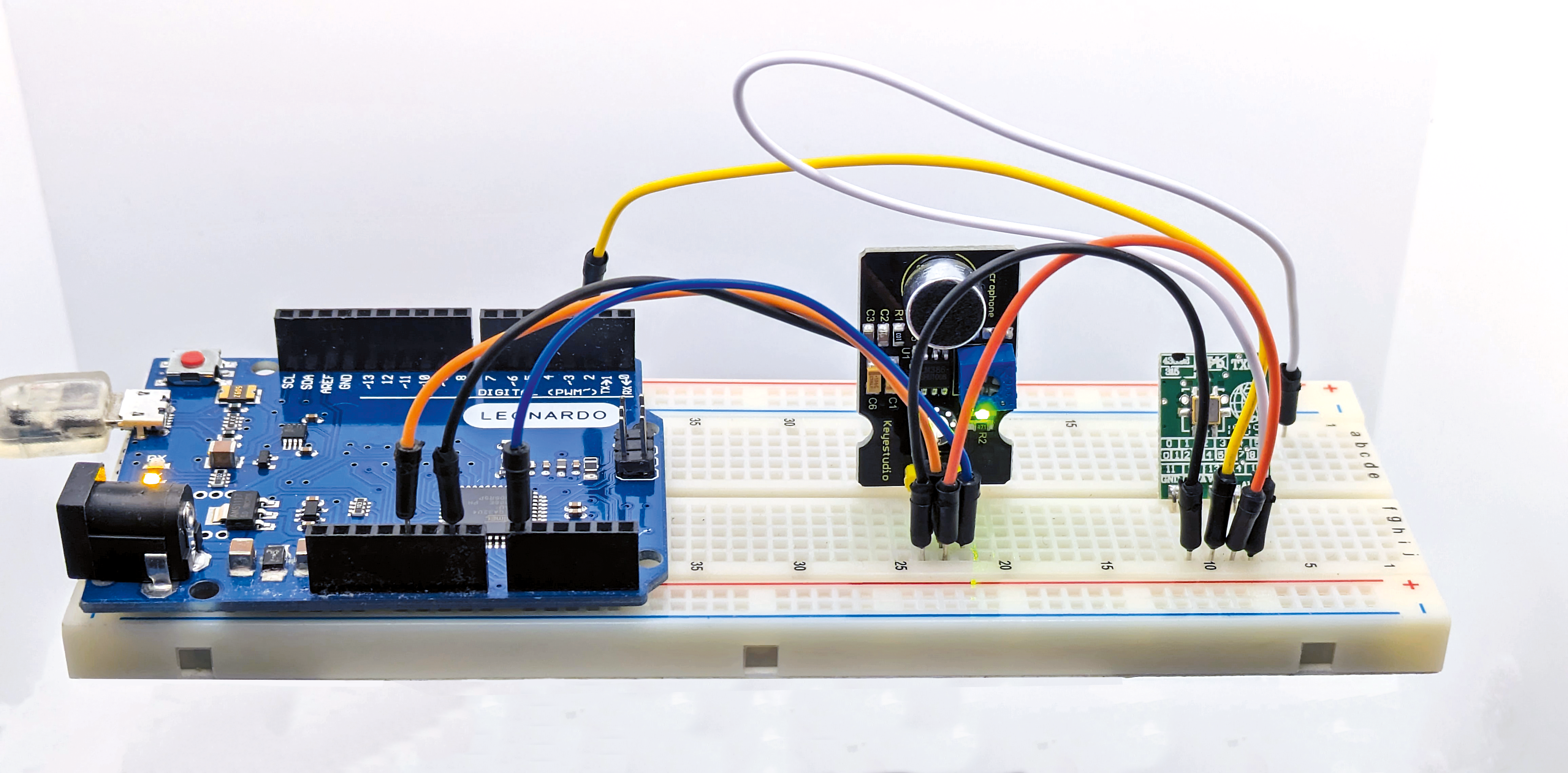
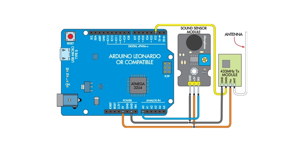
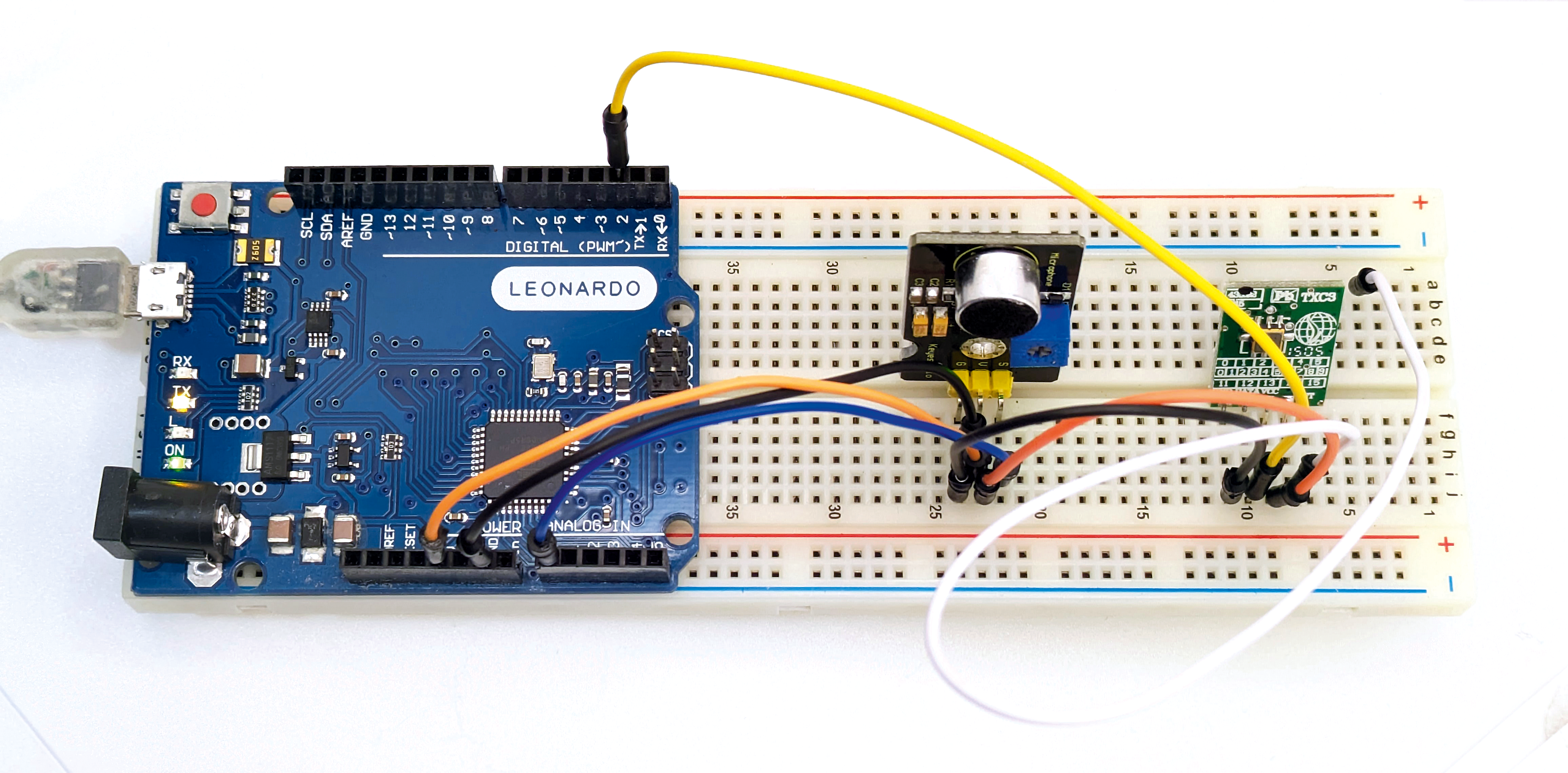
| 1 | Arduino Compatible Microphone Sound Sensor Module | XC4438 |
| 1 | Wireless Modules (Transmitter) - 433MHz | ZW3100 |
| 1 | Solderless Breadboard with Power and I/O Breakout Board | PB8819 |
| 1 | USB A to USB Micro B Cable 150mm | WC7757 |
Table of Contents

Future Improvements
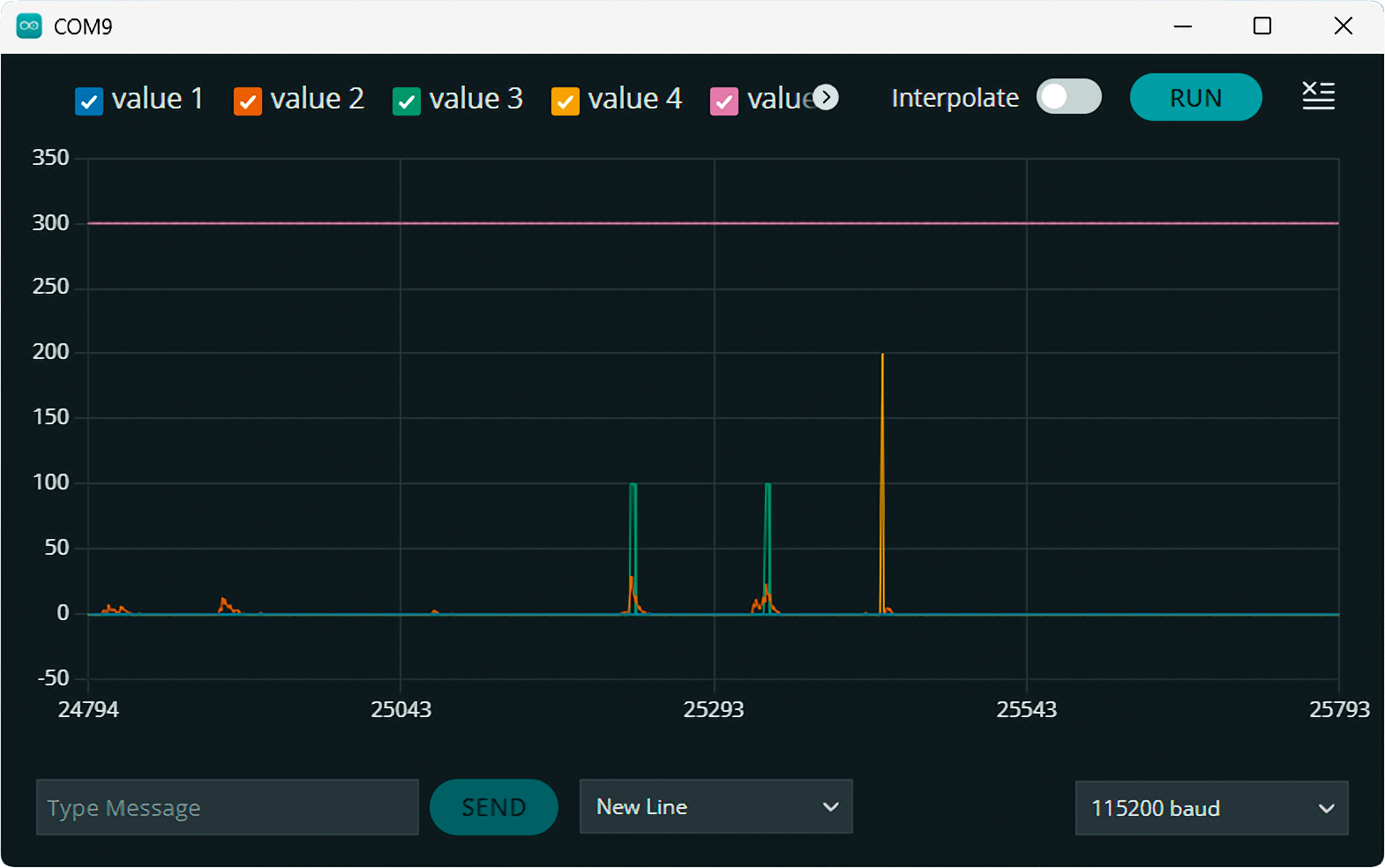
The Clap Light is quite accurate, but we found it still occasionally reacted to other sounds. For this reason, we have avoided making it respond to single claps. We recommend you do the same and also be careful not to connect anything that might be dangerous if unexpectedly turned on or off.
Some devices have integrated IR receivers, so they could be controlled by adding an IR transmitter. The sketch could easily be adapted to control low-voltage items via a relay module. Adding the Jaycar XC3730 LED Matrix Shield would allow you to add multi-coloured lights to the Clap Light.
This article appeared in the June 2024 issue of Silicon Chip Magazine. Check out their website for other project ideas: https://www.siliconchip.com.au/
Similar projects you may be interested in


